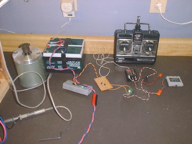
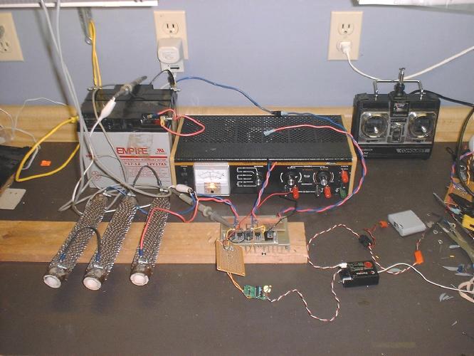
I finally cleaned off my work bench so I could do some real testing.
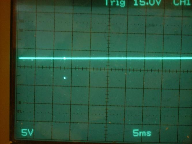
I used my "one fet" driver and 2 - 24V 7Ah gelcells. I started by just
running one of the 30V Ametek motors. I took some pictures of
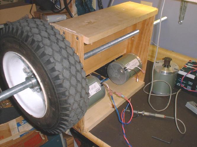
the oscilloscope. But the motor didn't draw much current. So I put my
plywood RoboWar prototype on the bench so I had something to
grab on to. It has a 12" diameter tire off my Earth Explorer. So I powered
it up and took some more pictures. The final torque on
the wheel is alot less than I expected when running at 24V.
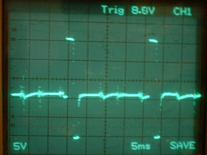
Then I hooked up some power resistors. I have 3 - 0.33ohm power resistors.
They look like they are about 300 watts each. So I wired
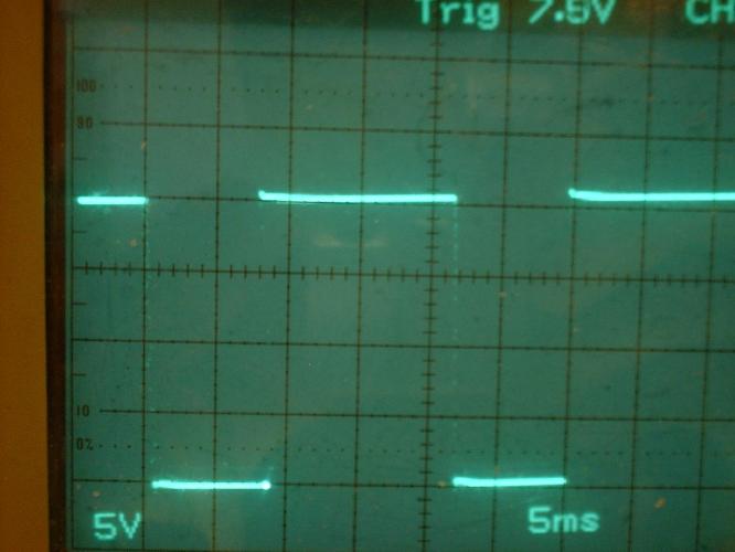
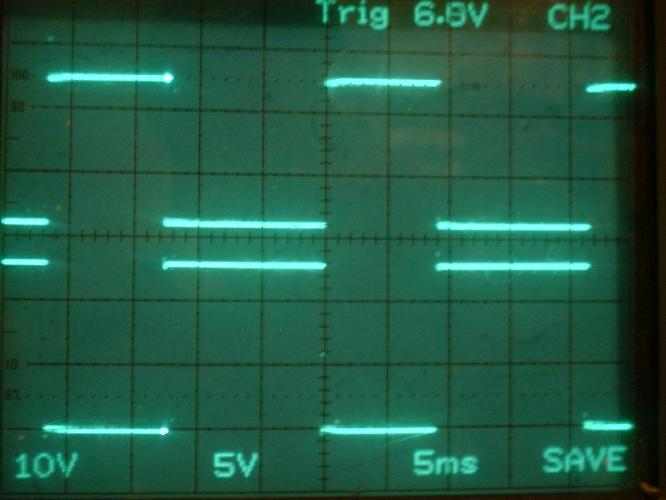
them in series to get approximately 1 ohm. The waveforms were nice and
square now. I ran it at about 10% duty cycle. Then ran it up
to about 50%. Nothing was melting down so I went up to about 95%. I could
smell my resistors and I didn't want to touch them. The
heat sink was warm, but not hot. It was two or three times warmer than my 16
gauge wire.
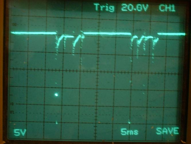
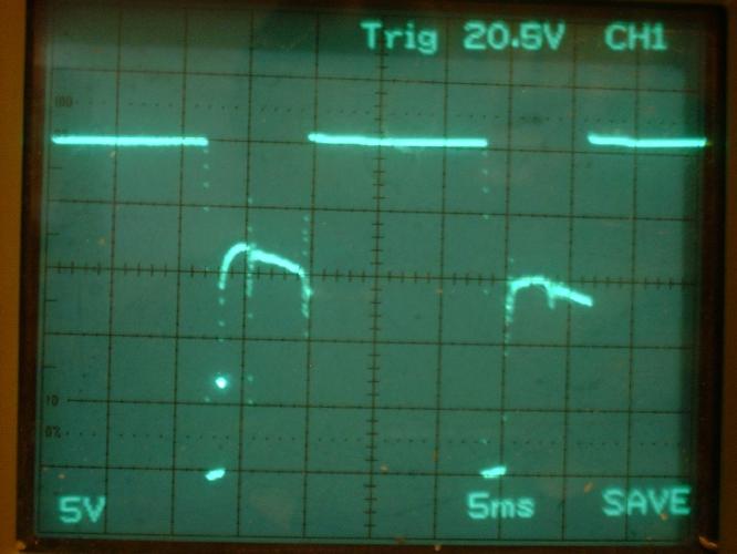
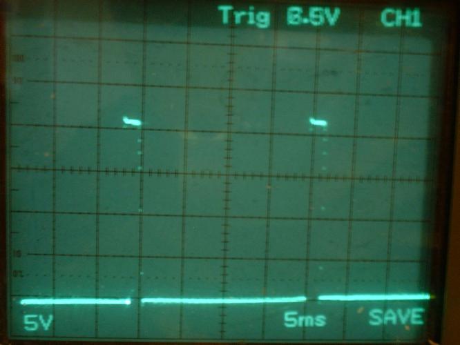
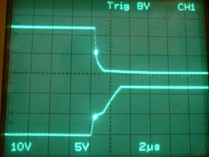
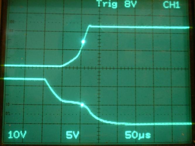
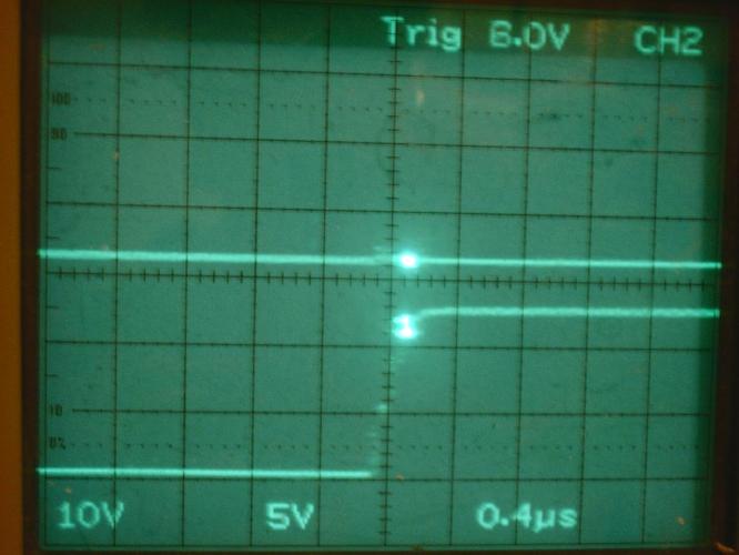
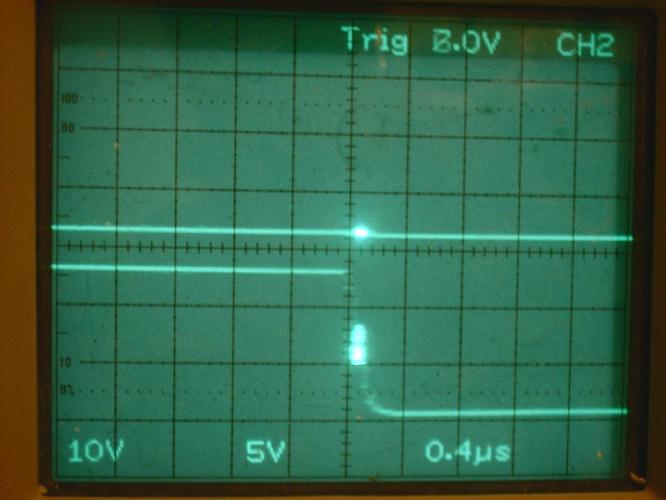
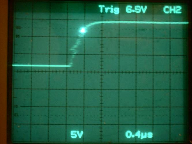
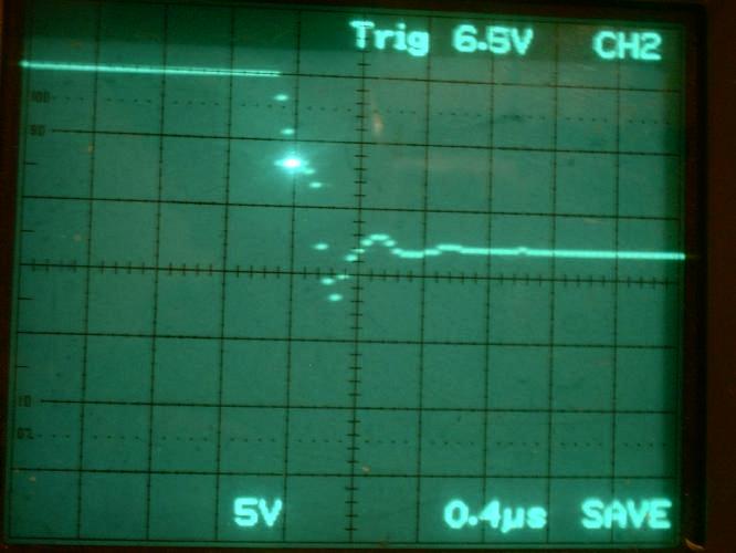
I took some pictures of the gate waveform vs. the output wave form. And sure
enough it is alot slower than it should be. (But I'm
not surprised considering how I am driving it.) The turn on is about 3us and
the turn off is about 150us. The FET is turning on and
off faster than that.
But I noticed my 7Ah batteries aren't holding up as well as I hoped. So I
now have my 18Ah batteries wired up. So I will go run some
more experiments.
I will try to get some pictures on my web site before the night is over.
--
Jeff Sampson
Subject: [TCRG] First casualty
Date: Mon, 09 Apr 2001 17:39:30 -0500
From: Jeff Sampson
To: "tcrobots@orbis.net"
Boy, MOSFETs sure stink when they go up in flames!!!
I left the driver running at about 90% PWM. I wanted to see if the heat sink
would heat up if I left it running. I went back
downstairs after 5 or 10 minutes and it was still running and the resistors
smelled REAL hot. Just about then I heard the tell-tale
PFFFFFT... And I had real pretty yellow flames coming out of my FET with the
usual white smoke spewing out. About then I thought,
"Hmmm... No fuses, I guess I better unhook the battery."
So I go it unhooked and checked the temperature of the heat sink. It was
real hot. I guess I need to drive the gate a little harder.
:-) And maybe that will taech me to not walk away from my power experiments.
PS. It really stinks down there now...
--
Jeff Sampson
Subject: Re: [TCRG] Motor controller experiments
Date: Tue, 10 Apr 2001 00:42:08 -0500
From: Jeff Sampson
To: "tcrobots@orbis.net"
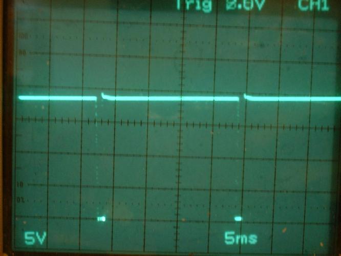
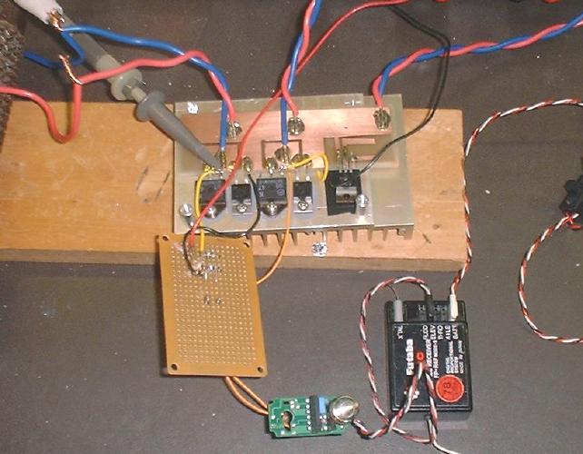
I have my version 3 MOSFET driver wired up. It uses a Telcom TC4427 dual
MOSFET driver. I ran it without the battery supply hooked up. I am
getting a rise and fall time on the gate of 200ns. Much better than 3us
rise and 150us fall times.
So my next step is to connect the battery and attempt to blow up another
FET. ;-)
--
Jeff Sampson
Subject: Re: [TCRG] Motor controller experiments
Date: Tue, 10 Apr 2001 03:26:50 -0500
From: Jeff Sampson
To: "tcrobots@orbis.net"
I added a bunch of pictures regarding my latest experiments:
http://www.citilink.com/~jsampson/tcrobowar/motor1/tst.htm
I haven't added all the pertinent descriptions yet.
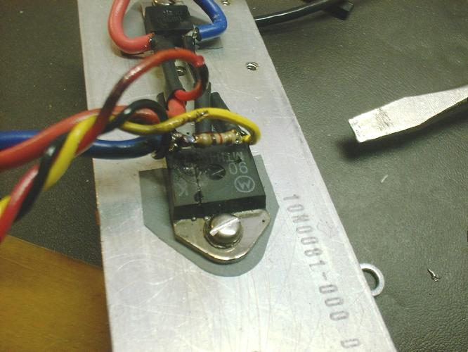
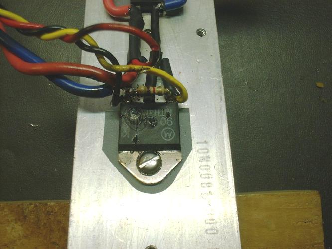
I haven't decided if the first FET blew up because of sloppy gate drive
(probably) or because it wasn't screwed down tightly or it just got too
hot. I noticed the screw was loose when I was doing the post-mortem. But
I also noticed the plastic shoulder washer had melted slightly. So maybe
it was tight to start with and the plastic melted out from under the
screw.
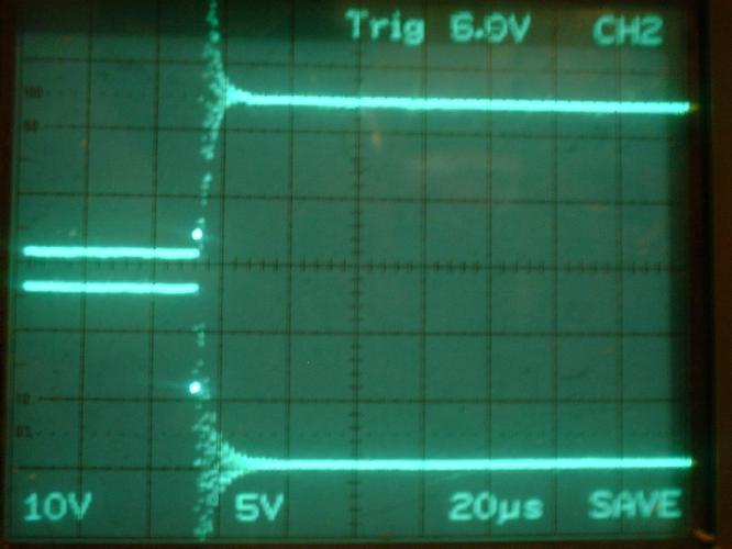
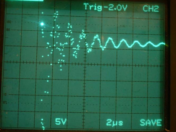
When I connected the battery for my new version the gate was ringing
REAL bad. I had forgotten to add a series gate resistor so I added a 10
ohm resistor. That didn't help much. I ended up adding a 1000uf cap
across the power input. (Which I should have had in the first place.) It
fixed the problem as you can see in the photos.
My new one runs hotter than I think it should. Let's see, 25 amps and a
.040 ohm FET. So 25 * 25 * .04 = 25 watts. The FET is quite warm to the
touch and the heat sink isn't getting hot. So either I haven't run it
long enough to heat up or the sil-pad is not transferring the heat.
Right off hand I don't know if a sil-pad is better or worse at heat
transfer than a mica insulator and heat sink compound.
But my R/C battery went dead and I had to stop experimenting. It gave me
time to build the web page with pictures.
--
Jeff Sampson