Previous | Index | Next
The Earth Explorer Project
Constructing the box for the base
I like the idea of prototyping my frames with wood. So I estimated the size that I would need and cut a piece of 1/2" plywood to the dimensions of 14" x 24". I cut four pieces of 1 x 6" pine boards to be used for the sides of the box. I then screwed these together with dry-wall screws. (Actually, I drilled the holes for the bearings before I screwed it together.) I learned from my many projects that unfinished wood gets dirty real fast. I also learned that trying to spray paint bare wood doesn't work well. So I applied a couple coats of sanding sealer.
The size of 14" x 24" x 6" for the box was not totally random. The height was determined by the components that had to fit inside. The main parts were the motors and the batteries. Even though the computer wasn't going in the bottom box, I kept in mind that I needed about 5" for a standard IBM motherboard with standard ISA slots. So the 1x6 boards gave me an inside height of 5-1/2".
The width was determined by the motor length plus some room for encoders. The encoders are some commercial units I found at ABC Electronics for $9.99 each. They are probably 500 lines/rev since there is a 500 in the part number. They have an etched glass disk with a real fine pattern. I didn't know the exact dimension, but 12-1/2" inside width looked like it would work. So with the two 3/4" sides it comes to 14".
The length was determined by the tire diameter which is 12". I was trying to make this thing as small as possible. Because my machines seem to get big and unwieldy quit quickly. So I looked at it for awhile and decided to have 2" between the tires. So the overall distance from the front tire to the back tire is 26". I decided to keep the box shorter than the tire length so I chose 24" for the box length. This works out well since it is able to climb obstacles, like the curb on the street, with out touching the box.
The drive system
This design needs two axles instead of one that the Yard Rover had. I used 3/4" steel rod for the axles and the reduction shafts. I originally used steel conduit clamps to mount the axles on the Yard Rover. That didn't work too bad, but I didn't drive it much. And when I did I wasn't rough on it. So I attached these the same way. I cut the chain to the appropriate length and installed it. Then I pulled the wheel towards me until the chain was tight. Then screwed the clamps down. This isn't the best way to insure your chain is tight, but it was OK for a test.
The first test
So I quickly bolted down the motors in a temporary location. It turns out the reduction shafts are too short to allow the encoders to fit. So I drilled random holes and bolted them down. We needed 24V to make it go. But we decided to use 12V since Alan's car was close. (We were in his garage.) I put a board on top of the box and sat on it. Alan connected a set of jumper cables to his car battery. Brynn was running the video camera. Alan asked if I was ready and I gave him the nod. He hooked it up and the motors tried to turn but didn't have enough torque. I was starting to get worried. We wired both motors to go the same direction and tried it again. It has plenty of torque to go straight.
Alan pulled out an old car battery he had stashed. We put it in series with the other one. He connected it again. This time the base started to rotate in a very graceful circle. All four tires squealing against the smooth concrete surface like you find in a garage. So I stopped worrying. The base with me (about 200lbs worth of me) was turning under it's own power. I don't plan to let it get that heavy, so I should be OK.
Ron showed up later with one of his wild projects. It may have been his Micro-light aircraft.
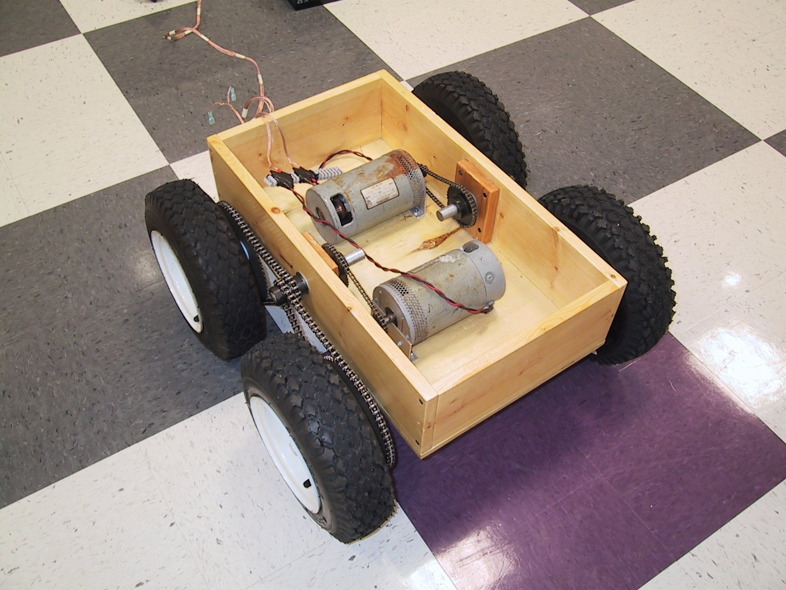
This is what it looked like for the first test.
This picture was taken at the June 2000 meeting.
I had a switchbox for the meeting to drive it.
Visit Twin Cities Robotics Group
Back to my Home Page http://www.pobox.com/~jsampson
This page is currently maintained by Jeff Sampson