Simplified video digitizer block diagram.
This page started on 01/03/01 and last updated 01/03/01
I have several things to decide. I have to decide which modules to build. How to physically construct the modules. How to interconnect the modules.
From the block diagram it looks like I need a video input module, a RAM module, a control logic module and a processor module.
I could start with any one of these modules. However with the recent discussion of programmable logic on the TCRobots list server , I decided that is where I should start. I need to decide what programmable logic I want to use, how to mount the parts, how it will fit with other modules and how I will connect it to other modules.
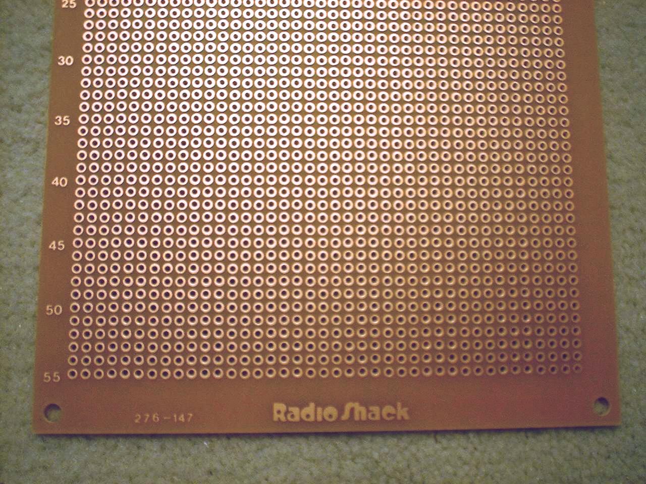
I have decided that I will have a "standard panel" for the board format. I will use the Radio Shack perf boards as my standard. (Radio Shack #276-147) I want to have a "full size" panel and a "half size" panel. This is the same concept they use with the xxx bus. Their card deck allows you to plug in a half size card, two half size cards or a full size card. I'm not planning on a card deck, my boards will lay flat on a plastic plate. A half size panel will be a full size board cut down the middle.

I was going to use the existing mounting holes as purchased. But it looked like it would be messy to get the holes to line up so I could mount either a half size board or a full size board. Then Ron pointed out that I could drill my own holes that will line up for either size board. So I will do that.
Another thing I need to standardize is the power connection to the board. It's not real critical, it just needs to get power. I've decided that I will supply power through a dedicated power connector. At the moment I am planning to put it at the top of the board.
Now how do I make interconnections that are easy to connect and reusable? I figure I have two basic types of connections to make. Individual connections and grouped connections. Examples individual connections would be chip select, reset, count, etc. Examples of grouped connections would be data bus, address bus, I/O ports, etc.
So what size do I make my grouped connections? I could make them 2, 4, 6, 8, 16, 24... Different sizes would have their benfits and faults. 8 bits would be good for a data bus. 16 bits would be good for an address bus. Various types of devices may prefer either 2 bits or 4 bits. After lots of thought I decided I should group them as 8 bits per connection. This allows quick connection of anything requiring 8 bits. I can simply use two 8-bit connectors to do the 16-bit address busses. I decided that a standard 10-pin (2x5) dual row header for the 8 bit block. That way I can use a 10 connector ribbon cable to make the connection. I haven't decided what to do with the extra 2 pins.
So what about signals requiring fewer than 8 bits? Their are a couple of ways to handle this. First is to use single wires to make the connections. These would be individual wires with a female socket on each end. As long as they are end/edge stackable then I can use any standard .1" spacing pin type connector. The other option is to use AMP MTx connectors. These plug into the 10-pin headers and accept individual wires. These can then be routed to any destination pin that is required.
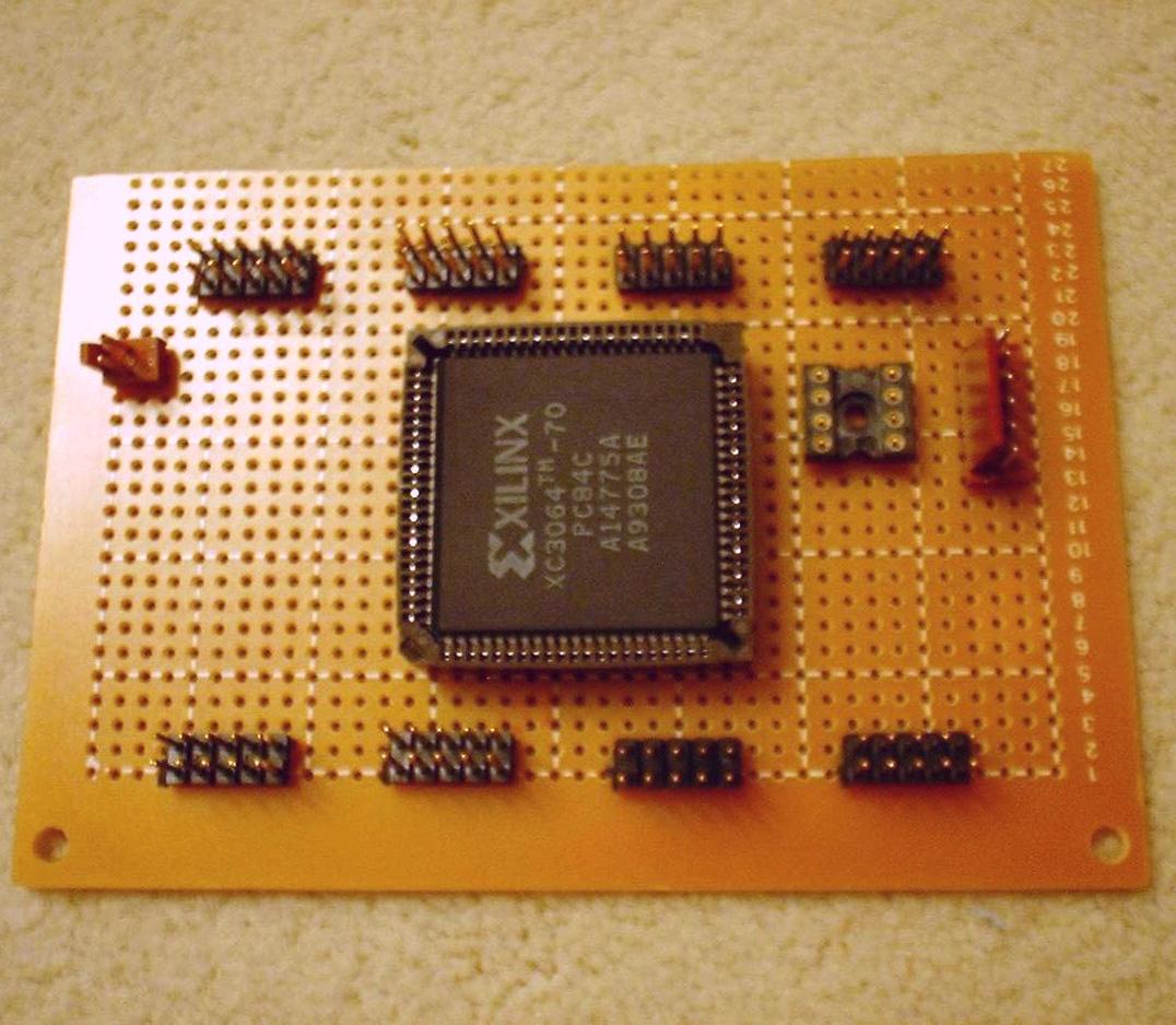
I gave some thought to what programmable logic part I wanted to use. I have used the Xilinx XC9536-44PC CPLD on my first digitzer. Dan and Bryan from TCRobots group are using the Xilinx XC9572-84PC and XC95108-84PC CPLDs. I decided the 84-pin part made more sense for a reusable module than a 44-pin part did. But I also have some Field Programmable Gate Arrays (FPGAs) that I removed from some surplus boards. I have a Xilinx XC3064 FPGA. It has approximately 4 times as many gates and 6 times as many flip-flops as does the XC95108 CPLD. The 3000 series are not programmable with the free WebPack that Xilinx recently released. But I have the $95 starter package that will do the 3000 and 4000 series up to 8000 gates. So I think I will go with the XC3064 FPGA.
The XC3064 has 70 usable I/O pins. So if I use them in groups of 8 I have 8 connectors plus 6 left over. I will have to check to see which I/Os are special purpose, like global clocks, and reserve them as my extra pins.
I also need some support for the FPGA. I already mentioned the power connector for the board. The FPGA has 3 configuration bits. I will add a DIP switch for this. The FPGAs are RAM based and get loaded each time the power is applied so I need to add an 8-pin socket for a serial configuration EEPROM. I will also add a 6-pin connector for doing J-TAG programming. This allows you to download directly to the FPGA during development. I can program the configuration EEPROM when I am satisfied with the logic design.
So the FPGA module will look something like this:
Visit Twin Cities Robotics Group
Back to my Home Page http://www.pobox.com/~jsampson
This page is currently maintained by Jeff Sampson